Not Available in the U.S.
This product is no longer offered by Intepro Systems in the United States. Should you need technical assistance, we will continue to support our products through our support section.
This product is no longer offered by Intepro Systems in the United States. Should you need technical assistance, we will continue to support our products through our support section.

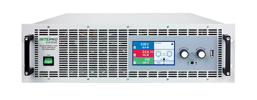
The FPGA based control circuit provides additional features, such as a function generator, a table-based regulation circuit for the simulation of non-linear internal resistance. The energy recovery function converts the supplied DC energy into a synchronous sine current and feeds it back into the local grid. This eliminates the usual heat dissipation to a minimum and saves energy costs at the same time. The large color TFT touch panel offers a different and intuitive kind of manual operation, compared to other devices. Response times for the control via analog or digital interfaces have been improved by the FPGA controlled hardware. In parallel operation of multiple devices, a master-slave bus is used to connect over 64 units in parallel for over 1MW.
Up to 2000 V
Extra USB port on the front for USB stick

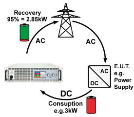
The most important feature of the ELR series is that the AC input, i.e. grid connection, is also used as the output to recover loaded energy with approximately 95% efficiency. Recovering loaded energy reduces energy costs and avoids expensive cooling systems that are commonly required for conventional air-cooled and water-cooled loads that dissipate energy in the form of heat. Please download our ROI Calculator in MS Excel to find out how much you can save


The standard regenerative function converts the supplied DC energy into a synchronous sine wave current and feeds it back into the local grid. This eliminates the usual heat dissipation to a minimum and saves energy costs at the same time.
The large LCD touch panel offers a modern and intuitive user interface for controlling the four operating modes, Constant Voltage (CV), Constant Current (CC), Constant Power (CP) and Constant Resistance (CR). Response times for the control via analog or digital interfaces by the DSP controlled hardware are among the fastest in the industry. In parallel operation of multiple devices, a master-slave bus is used to connect the chassis to create a high power system where the actual values are totaled and the set values distributed.
The available voltage range portfolio for the ELR 10000 programmable load goes from models with 0…60 V DC up to models with 0…2000 V DC. Input currents up to 1000 amps per chassis are also available. The series offers 30 kW in a compact 4U package, which can be extended up to 1080kW (or higher) in cabinets for a significantly higher total current. Please contact Intepro systems for higher power solutions.
Manual operation is done with a Gorilla glass touch panel, two rotary knobs and a push-button. The large color display shows all relevant set values and actual values at a glance. The whole setup is also done with the human-machine interface, as well the configuration of functions (square, triangle, sine) etc. The display is multilingual (German, English, Russian, Chinese).

The “Share Bus” is an analog connection at the rear of the devices and is used to balance current across multiple similar units in parallel connection, such as with loads of this series and series ELR 9000. It can also be used to build a two-quadrants system in connection with our PSI 9000, PS 9000 and PSB 9000 Series DC Supplies. This system is dedicated for testing purposes using the source-sink principle.
For purposes of testing all kinds of batteries, such as for example constant current or constant resistance discharging, the devices offer a battery test mode. This mode shows extra values for elapsed testing time and consumed capacity (Ah). For more detailed setup, there is also an adjustable threshold to stop the battery test on low battery voltage, as well an adjustable maximum test period. In order to simulate a solar inverter, the devices feature a function called “MPP tracking”, which is used to track and find the MPP (maximum power point) of the connected solar panel.
As for remote control, there are by default three interface ports (1x analog, 1x USB, 1x Ethernet) available on the rear of the devices, which can also be extended by optional, pluggable and retrofittable, digital interface modules (dedicated slot). Alternatively, to the interface modules slot, all models can be equipped with option 3W (see below), which then offers 1x GPIB/IEEE, 1x USB and 1x Analog on the rear side of the device. For the implementation into the LabView IDE we offer ready-to-use components (VIs) to be used with USB, RS232, and GPIB. Other IDEs and interfaces may be supported upon request.
Windows users can profit from the free software “Power Control”. It offers a feature called “Sequencing”, where the device is controlled through a semi-automatic table in CSV format. This table represents a simple test procedure and can be created and edited in MS Excel or other CSV editors and then imported into the software tool. This software also allows for the control of up to 20 units at once with an optional feature called “Multi Control” (licensed, not free of charge).

