Discontinued
Should you need technical assistance, we will continue to support our legacy products through our support section.

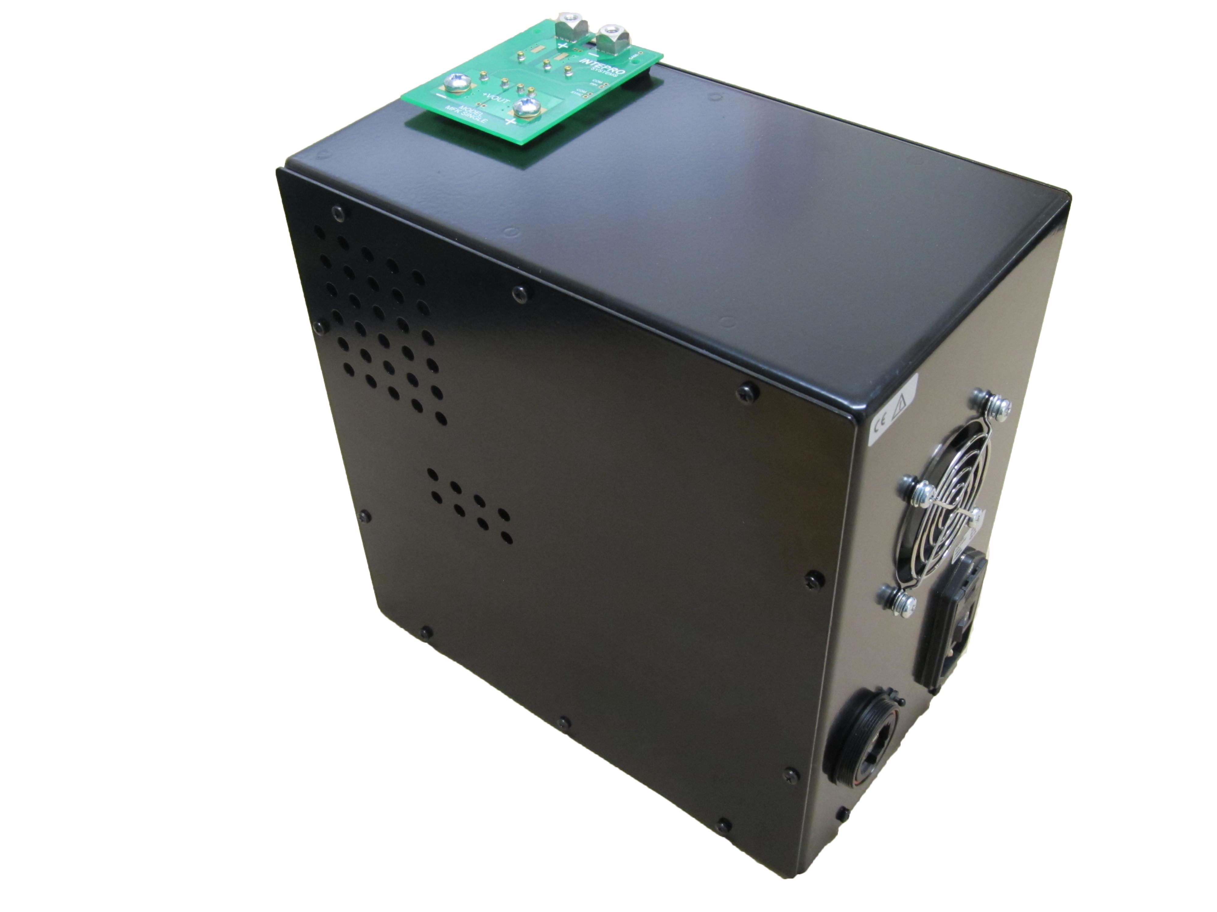
The smart on-board load head minimizes inductance, resistive losses and noise associated with typical loads that use wires to connect the device under test (DUT) to the load. With the increasing demand for high speed semiconductors, operating voltages are decreasing for minimizing the heat dissipation in devices. (DISCONTINUED) Electronic Load is designed for sub 1V testing to meet the demands of low voltage devices.
Ethernet control and read back
Sinks full rated current with only 0.3V applied to load head

The EL 2000 HS dc electronic load provides a platform that is flexible using its smart on-board head design and modular load modules for positioning POL connections for minimizing inductance that will reduces the speed of current transitions, rate of change of current in that path (di/dt) (V = L*di/dt), faster current demands or pulses result in higher voltage drops for a given inductance. When you add the benefits of high speed control and sampling our loads offer full functionality for your testing needs.
Most conventional electronic loads with cables connections cannot meet the demands of high bandwidth power supplies. This is a very common problem with power supplies for military and commercial applications where the power supply is delivering power to RF modules. The EL 2000 HS high speed DC load is designed for all the factors that contribute to the inductive path to the load’s power section by utilizing POL /POU modules and low internal inductance. The overall inductance of the current path is reduced by designing for the following; the connection interface to the power supply under test, the power transmission path, the critical current path inside the electronic load and the component selection along the path inside the electronic load. As the voltage drop V along a current path is directly proportional to the product of the inductance in that path (L) and the rate of change of current in that path (di/dt) (V = L*di/dt), faster current demands or pulses result in higher voltage drops for a given inductance. Therefore, the faster the current demand the greater the voltage drop and hence lower the voltage actually seen across the load device. Low inductance allows for fast rise and fall times at low voltages.
Figure 1 and 2 are typical rise and fall times. Notice hat over and undershoot are minimized but the advanced control feedback loops.

