EL+ vAC/DC Full
Regenerative AC/DC Electronic Load
EL+ vAC/DC Full Regenerative AC/DC Electronic Load
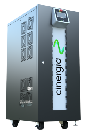
The Cinergia EL+ vAC/DC is the most versatile programmable DC electronic load and regenerative current source in the market for energy testing in AC and DC applications. Its Bidirectional and regenerative DC electronic load hardware, based on a back-to-back power conversion topology, allows saving energy and power. Thanks to its flexibility, this device becomes crucial in two main areas: testing and R&D. The main applications include Smart grids, Renewable Energy, Storage Systems, Electromobility, Avionics and Power HiL making it one of the leading AC electronic loads for industrial and R&D test environments.
The Cinergia EL+ is engineered for engineers and test labs that need a single regenerative electronic load capable of handling both AC and DC test scenarios with precise control over current, voltage, power, and resistance modes making it one of the most capable AC and DC electronic load testers available for renewable energy, EV, and grid simulation work. As a high-performance regenerative AC and DC electronic load, energy absorbed during testing is fed back to the grid, reducing operating costs and heat output without compromising test accuracy.
Featured Benefits
- Efficiency and Flexibility
- Save Energy, Power and Time
- Full options and power in AC&DC
- Smartgrids & Electrical Vehicles
- High-Resolution and Dynamics
Functionalities
- Bidirectional and Regenerative
- Clean grid current: THDi < 3% and PF > 0.98
- 13 models from 7.5kW to 160kW
- Emulation of grid-connected devices:
- Loads absorbing energy from grid
- Generators injecting energy to the grid
- Programmable Active/Reactive consumption
- Non-linear currents up to CF of 3
- Independent phase configuration of: rms current, phase angle, harmonics, interharmonics, generation of fast transients (“Current Dips”)
- Intuitive User Interface
- Modbus/Ethernet Open protocol, Labview drivers
Main Applications
 Electromobility
 Smart Grids
 Avionics
 IEC Testing
 Photovoltaic
 Power Hill
Local Interface
Analogue and Digital 10 ports
The isolated digital and analogue inputs/outputs permit the connection of the unit to External Controllers and Power Hardware in the Loop systems (option).
4.3" Touchscreen
Allows the local parameterization and command of the device, configuration of the communications link, plots the main signals and enables the local datalogging.
Safety First
The units integrate a local Emergency Stop pushbutton and two signals (input + output) to be connected to the laboratory interlock system. Additionally, the digital outputs can be interfaced to safety tower lights. These built-in protections make the Cinergia EL+ a safe and reliable programmable DC electronic load and regenerative electronic load for continuous and high-power test environments.
Master/Slave
ePLUS is a modular platform enabling the master/slave connection of units with equal power.
Options
Choose your options:
- Three channel mode: allows different operation mode start/stop/reset per channel (included in all models from 7.5 to 60, both included)
- 30kHz Switching Frequency: only available far models 15 (derated to 7.5kW), 20 (derated to 7.5kW) and 30 (derated to 10kW)
- Isolation monitor (advised far IT systems)
- Low current ripple inductance (included in all models ≤54kW. optional far models ≥80kW)
- High Frequency 360 - 900 Hz
- Anti-islanding monitor (only advised in net injection to the grid and following local regulations)
- High Voltage (HV): voltage up to 295Vrms phase-neutral in AC up to 800V in DC
- RS485
- Battery Emulation
- Battery Test
- PV Panel Emulation
Models
EL+ vAC/DC Full | ||||||
Reference | AC Power Rated | AC Current Rated (3 channels / 1 channel) | DC Power Rated | DC Current Rated (3 channels / 1 channel) | Weight (kg) | Dimensions DxWxH (mm) |
|---|---|---|---|---|---|---|
EL+7.5 vAC/DC | 7.5 kW | 11 A / 33 A | 7.5 kW | ±10A / ±30A | 155 kg | 770 x 450 x 1100 mm |
EL+10 vAC/DC | 10 kW | 15 A / 45 A | 10 kW | ±15A / ±45A | 155 kg | 770 x 450 x 1100 mm |
EL+15 vAC/DC | 15 kW | 22 A / 66 A | 15 kW | ±20A / ±60A | 155 kg | 770 x 450 x 1100 mm |
EL+20 vAC/DC | 20 kW | 29 A / 87 A | 20 kW | ±25A / ±75A | 155 kg | 770 x 450 x 1100 mm |
EL+30 vAC/DC | 27 kW | 40 A / 120 A | 27 kW | ±30A / ±90A | 155 kg | 770 x 450 x 1100 mm |
EL+40 vAC/DC | 40 kW | 58 A / 174 A | 40 kW | ±40A / ±120A | 200 kg | 770 x 450 x 1100 mm |
EL+50 vAC/DC | 50 kW | 73 A / 219 A | 50 kW | ±50A / ±150A | 200 kg | 770 x 450 x 1100 mm |
EL+60 vAC/DC | 54 kW | 80 A / 240 A | 54 kW | ±57A / ±171A | 200 kg | 770 x 450 x 1100 mm |
EL+80 vAC/DC | 80 kW | 116 A / - | 80 kW | ±105A / ±315A | 400 kg | 870 x 875 x 1320 mm |
EL+100 vAC/DC | 100 kW | 145 A / - | 100 kW | ±130A / ±390A | 400 kg | 870 x 875 x 1320 mm |
EL+120 vAC/DC | 108 kW | 157 A / - | 108 kW | ±130A / ±390A | 400 kg | 870 x 875 x 1320 mm |
EL+160 vAC/DC | 145 kW | 211 A / - | 145 kW | ±155A / ±465A | 680 kg | 850 x 900 x 2000 mm |
EL+200 vAC/DC | 160 kW | 232 A / - | 160 kW | ±185A / ±555A | 680 kg | 850 x 900 x 2000 mm |
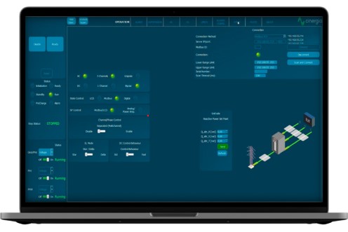
Software

The user interface used by CINERGIA devices has been developed by our R&D team, to offer total control of the device, with a comfortable and intuitive design. This allows us to take full advantage of the capabilities of the device, as well as the programming and execution of standardized or self-created tests.
EL Modes

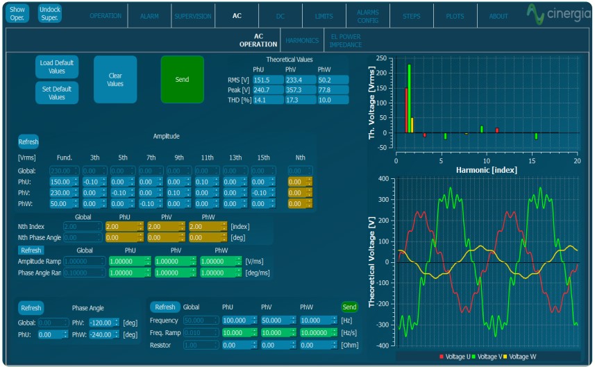
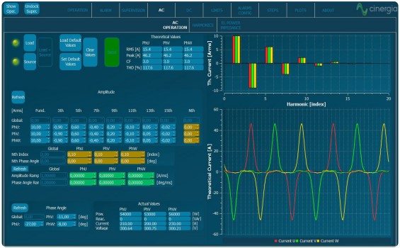
AC Operation
From this panel, the user can set all AC parameters. Each phase can be independently configured: RMS current magnitude, phase delay, harmonics content, free-frequency harmonic and transition ramps. A plot shows the expected real-time waveform, the FFT representation and the numeric data: RMS, peak, CF and THD.
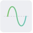
Harmonics
The device can control simultaneously the magnitude of the first 15 harmonics and one free harmonic per phase. The free one allows the generation of sub-harmonics, inter-harmonics and high frequency harmonics up to the 50th, setting both the magnitude and phase delay.
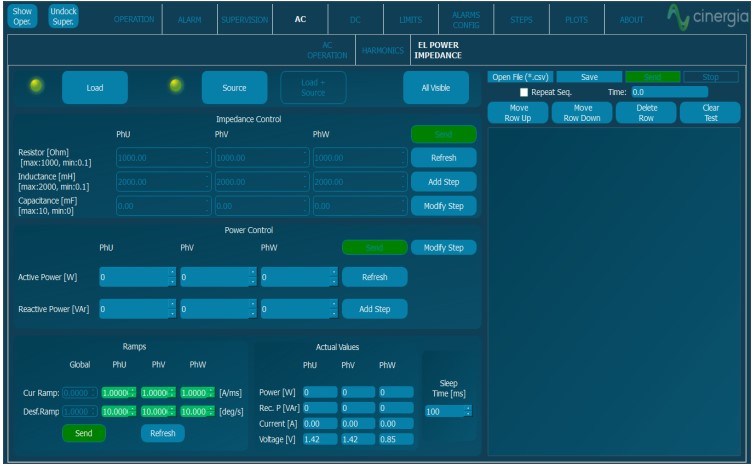
Power and Impedance Control
In Power mode, the active and reactive power of each phase is independently controlled. In Impedance mode, the device emulates an RLC load allowing to parameterize resistance, inductance and capacitance per phase making this device suitable for Anti-Islanding test of grid converters.
AC
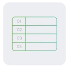
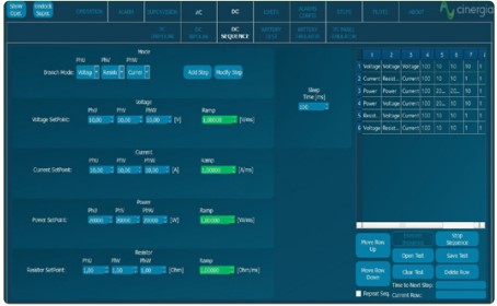
Steps Mode
One of the most remarkable novelties of the new software is the steps functionality. Step test files are saved and executed by the DSP allowing deterministic timing with a resolution of 66µs. The user gains access to all registers of the device to create complex test sequences which run directly in the converter without the need of an external computer.
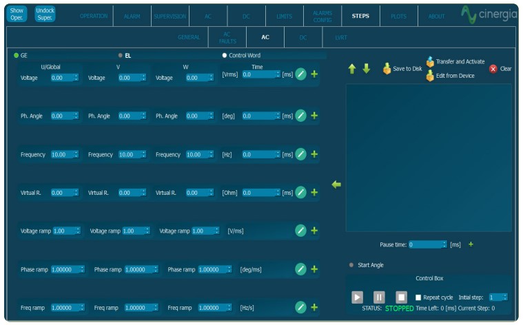

Disturbance Generation
The steps mode includes predefined easy-to-use test panels. The AC faults panel is a powerful yet intuitive editor which allows generating and configuring flicker. Specific profiles can be saved in .csv files, modified, and reused by importing an existing one.
Linear & Non-Linear Emulation
The capacity to emulate linear and non-linear loads in one of the main features of the 4Q Electronic Load. Through our intuitive control software, the magnitude of harmonics can be set and different types of loads can be generated.
DC

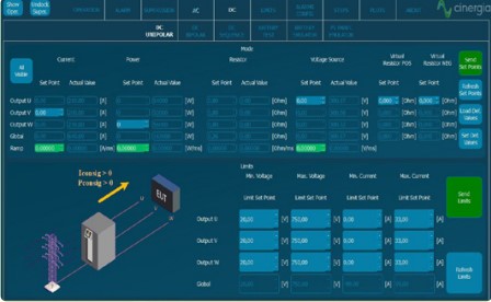
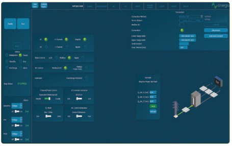
DC Operation
This panel allows the user to access all DC setpoints and limits. Thanks to the unique Multichannel feature, each phase can have a different Operation Mode: voltage, current, power, resistance and advanced DC applications. Transition ramps, voltage and current limits can be modified. The limits for sink and source operation are different for safer testing, specially in battery applications.

Sequence
The User Interface Software integrates a Sequence Editor to create automatic test sequences, save them for future use and import them in .csv files. A smart datalogger can be activated from the LCD of the unit to record automatically the resulting voltage and current measurements with a time resolution of 400 ms.

Multichannel
Enabling the Separated Channel Control converts the device in three functionally independent DC Bidirectional Power Supplies, sharing the common negative rail. Each channel can have a different status (ON, OFF, Warning, Alarm), Operation Mode (see Range and Specifications table), Setpoint, Ramp and Limits.

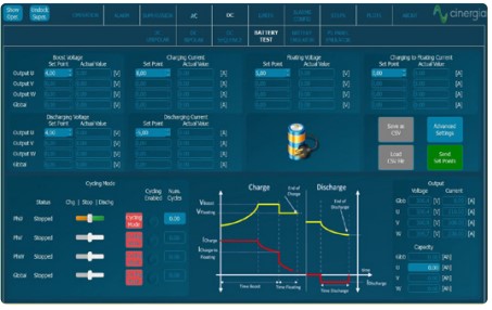
Battery Pack Tester
This functionality enables the user to precisely control the charge, discharge and cycling of a Battery. Basic paramters include the charge/discharge current, fast charge and floating voltages while Advanced parameters add Energy (Ah) and Time as transition conditions. Prof iles for each Battery technology can be saved and imported in .CSV files.
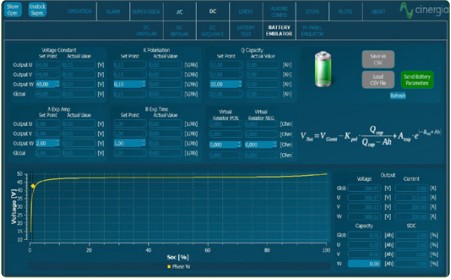
Battery Emulation
The B2C+ integrates a mathematical model to emulate the voltage behaviour of a real battery pack. The output voltage will change as a function of the SOC and Current. By confi guring the provided parameters, the voltage profi le can be adjusted to match different technologies: LiIon, NiMH, NiCd, Pb, Flux, etc.

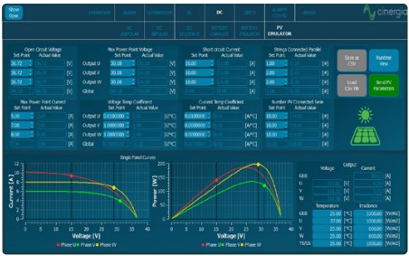
PV Panel Emulation
The PV Panel model is based on the single-diode equivalent circuit of a PV cell and the series-parallel connection of cells to form a panel. A Runtime functionality allows the simulation of a complete day by launching different irradiance and temperature setpoints from a .csv f ile, enabling the user burn-in and functional tests of PV Inverters.
Need to compare products?
Request a Quote Today
FAQ
The EL+ vAC/DC is a programmable, full regenerative AC/DC electronic load designed to test AC and DC power sources, inverters, UPS systems, and renewable energy systems by dynamically loading and regenerating absorbed energy back to the grid.