Press Releases
Intepro Systems News
Electric vehicle motor control unit test

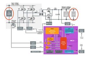
Figure 1 is an example of a typical MCU. Typical EV batteries operate at a nominal 360 Vdc with a high line of 403 Vdc. Battery power is then provided to the power source which is controlled by the MCU. The MCU provides a PWM signal to the power source which amplifies the signal to the motor (or load). The challenge in testing an MCU is creating repeatable test results using actual batteries and motor. Batteries require charging, discharging, take-up valuable lab space and at 360V and up to 90kW are lethally dangerous to use, and potentially lethal.
Figure 1: Typical MCU Layout Likewise, using an actual motor requires the motor to be loaded by a ‘dyno’ to simulate real world driving conditions. This entire set up is cumbersome and makes it difficult to create repeatable test results. This application note describes how to use a programmable DC source to simulate batteries and DC loads to simulate the motor.
More information

Download the full application note which describes how to use a programmable DC supply to simulate batteries, and DC loads to simulate the motor.
Products
Support
Company

